Using the IMU/AHRS with YachtBot
YachtBot's AHRS (attitude and heading reference system) option includes a 9 degrees of freedom (9DOF) AHRS inertial and magnetometer system which provides GPS time synchronised orientation estimations as well as raw kinematic sensor data at rates up to 200Hz.
GPS rate HDGM (magnetic heading) information, from the orientation estimation, is available for visualisation on the YachtBot web portal or via the Igtimi API for cloud based data access.
Full rate orientation and kinematic data may be logged in a NMEA format compatible CSV logfile.
Orientation estimation
The goal of orientation estimation is to report the attitude of YachtBot relative to the frame defined by the earth's surface and magnetic north. Orientation can be reported as Euler angles or Quaternions and the "zero" orientation is when YachtBot's mounting frame of reference (see Mounting options) is flat to the earth and pointing north.
The orientation estimation uses an algorithm that includes Kalman filtering techniques. Raw sensor data input is oversampled, and final estimations low pass filtered to remove unwanted impulse noise and vibration.
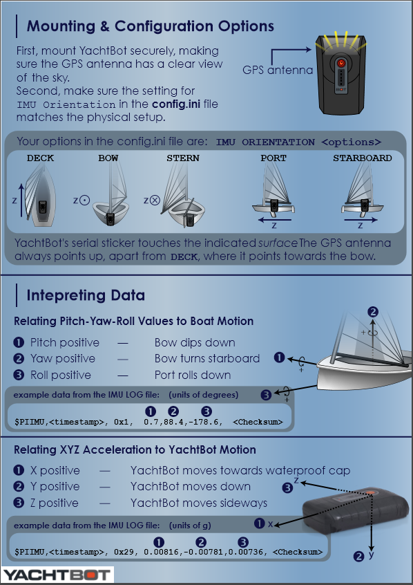
Mounting options
YachtBot can be mounted in several different orthogonal orientations which are configured via the
IMU AXES \[DECK/BOW/STERN/PORT/STARBOARD\]
command. The argument describes the surface of the object that the rear surface of YachtBot is to be mounted against. The GPS antenna should always be pointing up, except for DECK mount, where it should be pointing towards the bow. The option only affects the orientation data, not the kinematic data.
Raw kinematic data
Linear acceleration and gyro information may be logged. Linear acceleration can be logged with, or without the static gravity vector included. This is not affected by the mounting option and will use the natural axis of the IMU. For details about the natural axis refer to the attached pdf on mounting options: Yachtbot Mounting options
Calibration and accuracy
The AHRS has been factory calibrated to correct for linear and non-linear errors in the sensors. Each YachtBot passes calibration testing if 4-points static heading errors are less than 0.5 degrees in a ferritic-free environment.
Zero point offset
First order Euler angle offsets can be set using the
IMU PYR
command, and can account for any fixed offset errors due to remaining zero offsets in the orientation estimation, or due to mounting alignments. Note that a first order correction is only suitable for small corrections. Where large mounting errors are present, post-processing rotation of the orientation estimation is recommended. Note that the Euler angle orientation estimation outputs with non-orthogonal mounting are still valid, but the parameters no longer map directly to the physical properties expected of Pitch/Roll/Yaw. See Yachtbot Mounting options
Drift and zeroing of the reference frame
YachtBot estimates reference vectors that define the orientation of the earth frame. These reference vectors are determined at power-up and continuously corrected. To
ensure that the reference vectors are correctly determined, it's important that YachtBot should be powered up while stationary.
Magnetic declination
Orientation is measured relative to magnetic north. The angle between magnetic north and true north is called magnetic declination. Where yaw/heading needs to be
referenced to true north, using NOAA's empirical declination model is recommend.
http://www.ngdc.noaa.gov/geomag/geomag.shtml
Live Data
Magnetic heading (HDGM) is transmitted live to the YachtBot server directly using the Yaw field from the Euler angle output. To enable HDGM output in YachtBot, Euler
angle messages must be enabled and the mounting configuration correctly configured. The maximum rate for HDGM data is defined by the GPS rate, and it is
recommended to set the Euler angle message rate at the same rate as, or multiple of, the GPS rate. An example enabling the Euler message for HDGM is:
IMU MESSAGE EULER 1 log 1 live
which would set the eular rate to that of the IMU.
Logfile
AHRS data is logged to \
An example of the logfile is;
$PGSNC,24391,2013-11-28T21:40:57.886Z,DC-DK-AADK,0xa2\*71
$PIIMU,24390,0x1,-6.0,-139.1,-0.2,\*00
$PIIMU,24500,0x1,-5.9,-139.0,-0.2,\*04
$PIIMU,24750,0x1,-6.0,-138.9,-0.1,\*02
$PIIMU,25000,0x1,-6.0,-138.8,0.0,\*2C
$PIIMU,25250,0x1,-5.9,-138.8,0.1,\*20
The fields are;
| $PGSNC | Header indicating Proprietary GNSS SyNC message |
|---|---|
| 24391 | System timer in milliseconds |
| 2013-11-28T21:40:57.886Z | ISO8601 timestamp |
| DC-DK-AADK | Device Serial number |
| 0xa2 | Device Stream ID, in hex |
| *71 | NMEA compliant CRC |
| $PIIMU | Header indicating Proprietary Inertial message from an IMU |
| 24390 | System timer in milliseconds |
| 0x1 | Message identifier (Euler angles) |
| -6.0 | Pitch |
| -139.1 | Yaw |
| -0.2 | Roll |
| Blank field to assist CSV processing | |
| *00 | NMEA compliant CRC |
For detail on the message types, values, field order and sign conventions, see the appendices below.
Configuration
The following is a typical configuration block for the AHRS. Note that the term IMU is used to reference configuration of the AHRS system in the configuration.
\## IMU
##
#
IMU rate 4
IMU message euler 4 log
IMU message quaternion log
#IMU message gyro log
#IMU message linearg log
IMU pyr 0 0 0
IMU on
IMU axes deck
IMU start
In words;
"Configure the IMU to log Euler angles at 1Hz, and Quaternions at 4Hz. Raw sensor data for gyro and linear accelerometer is disabled. No zero offset corrections are
set and the unit is expected to be mounted in the DECK orientation with the back of the device on a flat deck and GPS antenna pointing towards the bow".
Note that the order that some of the commands are issued is important. AXES and START commands must come after ON.
Commands
Arguments in square brackets are optional. A forward slash inside square brackets means "or".
For example, [DECK/BOW] means the argument is optional, or can be either DECK or BOW.
IMU RATE \[<rate>\]
Read (no args), or set, the native (maximum) query rate for IMU in Hz.
IMU MESSAGE <type> \[<divider>\] \[log\]
Read (no args) or set message types to query IMU for. The message type is requested at a rate defined by
Default argument values are
IMU MESSAGE <type> off
Disable querying IMU for message
IMU EULER PYR \[<pitch> <yaw> <roll>\]
Read (no args), or set, offsets that are added to Euler angles from the orientation estimation.
IMU AXES \[DECK/BOW/STERN/PORT/STARBOARD\]
Read (no args), or set, the installation orientation of YachtBot on the object to be tracked. The argument describes the surface of the object that the rear of YachtBot is to be mounted against. The GPS antenna should always be pointing up, except for DECK mount, where it should be pointing forward.
Logfile Synchronisation
For IMU logfile sync see Synchronisation mode
Appendix: Conventions and units
• Axis system is left handed with Z forward/north, Y up, and X right.
• Euler angles (more accurately Tait-Bryan angles) are reported in Pitch-Yaw-Roll order.
• Quaternions reported in XYZW order.
• Linear accelerations are reported in XYZ order.
• Gyro is reported in XYZ order.
• Units
○ Euler angles; degrees
○ linear acceleration; g
○ Gyro; rad/s
Appendix: Signs
The following table outlines the sign conventions where IMU data is used.
• Axis and natural sign means behaviour of the field with respect to the frame of YachtBot.
NEMA means the sign convention for where the data is translated to standard NMEA0183 messages created by YachtBot. For example where NMEA data is output
on the YachtBot serial output
• Logfile means as recorded by the $PIIMU message. Not to be confused with NEMA.
• API means as the data is recorded in Igtimi's API for use with YachtBot.
| Field | Axis and natural sign | NMEA | Logfile | API/YachtBot |
| Euler: Pitch | +ve for clockwise rotation looking back down x to origin | -180 to +180 +ve bow up | -180 to +180 +ve bow down | - |
| Euler: Yaw | +ve for clockwise rotation looking back down y to origin | 0-360 +ve turn right | -180 to +180 +ve turn right | 0-360 +ve turn right |
| Euler: Roll | +ve for clockwise rotation looking back down z to origin | -180 to +180 +ve = port up | -180 to +180 +ve port down | - |
| Linear/linearg | All fields +ve when accelerating back down axis to origin | - | As natural | - |
| Gyro | All fields +ve for clockwise rotation looking back down axis to origin | - | As natural | - |
Denotes fields where the natural sign has been reversed to match NMEA standards
Appendix: Data types
| Type | Description | Message identifier |
| Euler | Orientation as Euler angles | 0x1 |
| Quaternion | Orientation as Quaternions | 0x0 |
| Linearg | Raw (oversampled) linear accelerometer data | 0x27 |
| Linear | As above, without component of gravity | 0x29 |
| Gyro | Raw gyro data | 0x26 |